Raspberry Pi GPIO pins function as bidirectional communication pathways that respond to varying voltage levels, not just fixed digital signals. You’ll encounter two distinct numbering schemes—BOARD and BCM—that require precise configuration to prevent hardware damage. When you initialize these pins through libraries like RPi.GPIO, you’re establishing whether each pin will receive input from sensors or send output to actuators. Mastering these fundamentals opens the door to creating sophisticated automation projects without relying on pre-built modules.
Key Takeaways
- Raspberry Pi GPIO pins are programmable general-purpose input/output connections that operate at 3.3V logic levels.
- GPIO pins can be configured as inputs to receive signals or outputs to control components like LEDs.
- Two numbering systems exist: BOARD (physical pin position) and BCM (Broadcom chip-specific numbering).
- Programming GPIO pins requires libraries like RPi.GPIO with basic commands for setup and control.
- Always use protective components like resistors when connecting to GPIO pins to prevent damage.
What Are Raspberry Pi GPIO Pins and Why They Matter
While various components of the Raspberry Pi capture attention, Raspberry Pi GPIO pins constitute the fundamental interface that transforms this single-board computer into a versatile controller for physical computing projects.
These General Purpose Input/Output pins function as programmable digital signal interfaces that can be configured as either inputs or outputs through software control.
In GPIO usage scenarios, each pin operates at either HIGH (1) or LOW (0) voltage states, enabling bidirectional communication between your Pi and external hardware. GPIO pins can be monitored using pin listeners that react to state changes, making your projects responsive to input events.
The pins’ true power lies in their adaptability—they connect directly to sensors, actuators, and other electronic components without predetermined functions. They can be configured in multiple operation modes including input with pull-up/pull-down resistors and push-pull output configurations.
This flexibility drives countless GPIO applications, from home automation systems to robotic controllers, making them essential for innovators seeking to bridge the digital-physical divide in embedded computing projects.
Understanding Raspberry Pi GPIO Pins Numbering Systems
Before working with Raspberry Pi’s GPIO pins, you’ll need to master a fundamental aspect that trips up many newcomers: pin numbering systems. Two primary methodologies exist: BOARD (physical) and BCM (logical) numbering.
| Numbering System | Characteristics | Software Usage | Best Application |
|---|---|---|---|
| BOARD (Physical) | Sequential layout (1-40) | GPIO.setmode(GPIO.BOARD) | Hardware documentation |
| BCM (Logical) | Broadcom SOC mapping | GPIO.setmode(GPIO.BCM) | Software development |
| Pico GPIO | Direct GPIO0-29 labels | MicroPython pin() | Microcontroller projects |
| Special Function | I2C, SPI, UART designations | Library-specific calls | Protocol communications |
When implementing your projects, select the appropriate numbering convention in your software library. Physical layout references maintain consistency across board revisions, while logical mapping corresponds to the processor’s internal architecture. The 40-pin header allows for connecting various external devices to your Raspberry Pi. The Raspberry Pi Pico utilizes a straightforward arrangement with odd numbered pins placed on the left and even on the right. Mixing systems within a single program will generate errors, so maintain systematic adherence to your chosen convention.
Setting Up GPIO Pins for Input and Output

Two foundational operations define GPIO pin functionality: input and output configuration.
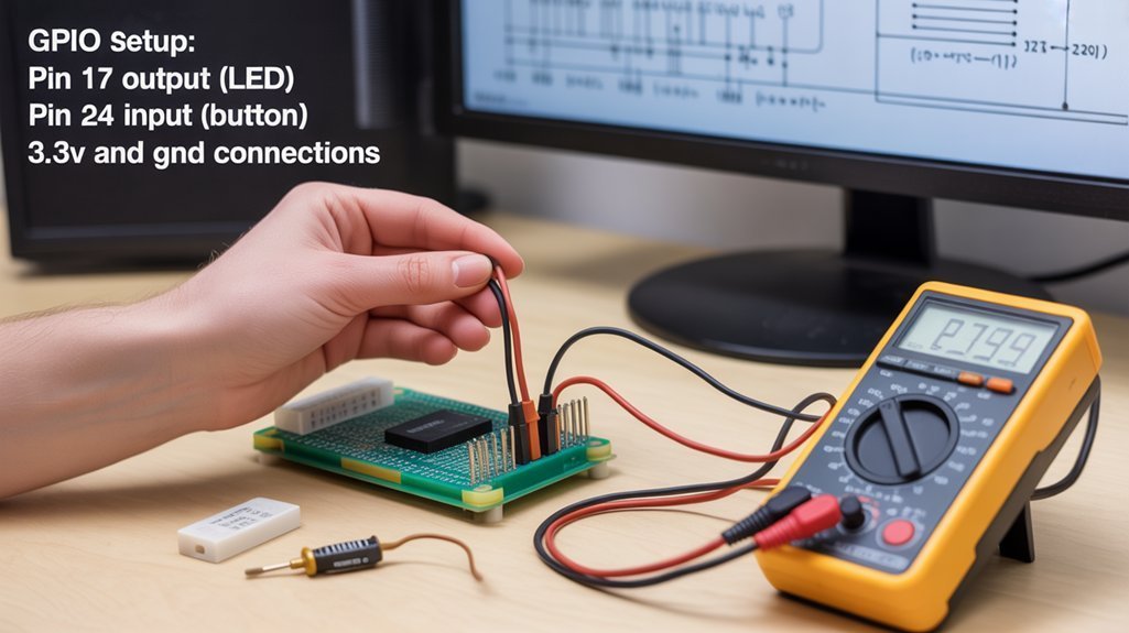
For input pin configuration, import the RPi.GPIO library and set your pin numbering system to BCM. Configure pins with `GPIO.setup(pin, GPIO.IN)`, implementing pull-up or pull-down resistors to stabilize signals and prevent floating states. Implement debouncing to handle button press fluctuations. Internal pull-up and pull-down resistors in the Raspberry Pi enable defined voltage states without external components.
For output pin control, use `GPIO.setup(pin, GPIO.OUT)` with optional initial state parameters. Control these outputs with `GPIO.output(pin, value)` to drive LEDs or other components. Connect outputs through appropriate current-limiting resistors for component protection. A 270 Ohm resistor is typically used when connecting an LED to a 3.3V GPIO pin output.
Combine input and output functionality using while loops to continuously monitor inputs and adjust outputs accordingly. Implement time delays with `time.sleep()` for debouncing, and structure conditional logic to process input signals effectively.
Common GPIO Projects for Beginners
Practical implementation of GPIO pins begins with several foundational projects that establish essential skills for more complex applications.
LED control represents the quintessential entry point—connecting LEDs to GPIO outputs with appropriate current-limiting resistors and implementing PWM for brightness modulation.
Button interfaces extend functionality by configuring pins as inputs with pull-up/down resistors and implementing debounce mechanisms to filter mechanical noise. Setting up Python correctly with proper permissions is essential for reliable button response in these projects.
Sensor integration introduces environmental data collection, requiring analog-to-digital conversion for non-digital sensors like photoresistors or temperature modules.
Motor control projects demonstrate power management concepts, utilizing H-bridge circuits or dedicated drivers to safely operate DC motors, servos, or steppers beyond GPIO current limitations.
Display projects incorporate I2C or SPI protocols to manage LCD/OLED modules, creating visual feedback systems that communicate sensor readings or system states efficiently. Python scripts like the “blinker.py” example can be executed using sudo commands to ensure the RPi.GPIO module functions correctly.
Safety Considerations When Working With Raspberry Pi GPIO Pins

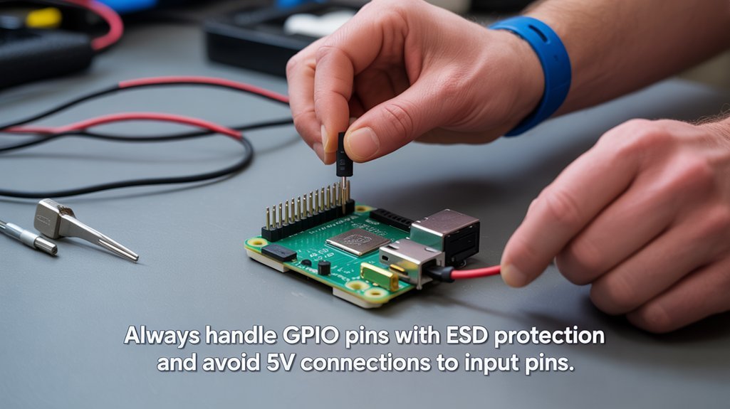
Safe operation of Raspberry Pi GPIO pins requires adherence to five critical parameters that prevent irreversible damage to your microcontroller. Never exceed 3.3V logic level on any pin or surpass current limits of 16mA per pin and 50mA total across the board.
Implement 220Ω-1kΩ series resistors to protect components. Proper wiring practices mandate verification of connections before powering up. Utilize pull-up/down resistors for input stabilization and avoid direct output-to-output connections. Before testing, it’s advisable to use a breadboard setup first.
Integrate protection circuits including flyback diodes for inductive loads and optocouplers for high-voltage isolation. Mitigate ESD risk by grounding yourself before handling components. Deploy anti-static equipment when possible.
Always power your Pi with regulated 5V supplies and incorporate voltage regulators to minimize noise fluctuations. Use a multimeter to verify that your power supply provides stable 5V output before connecting to your Raspberry Pi.
Frequently Asked Questions
Can I Power External Motors Directly From Raspberry Pi GPIO Pins?
No, you can’t power motors directly from GPIO pins. Their 3.3V/15mA limitations are insufficient for motor power sources. Always use dedicated motor drivers to protect your Pi from electrical damage.
How Do I Troubleshoot a GPIO Pin That Isn’t Responding?
Feeling like your GPIO’s giving you the silent treatment? Begin with systematic GPIO signal testing using a multimeter for pin voltage measurement, then verify code configuration, check physical connections, and reboot your system if necessary.
Are GPIO Pins Protected Against Voltage Spikes?
No, standard Raspberry Pi GPIO pins lack built-in voltage protection against spikes. You’ll need to implement external safeguards like TVS diodes or resistor networks to prevent electrical damage to your development board.
Can I Use GPIO Pins While Raspberry Pi Is Running Headless?
Imagine monitoring your greenhouse remotely: you can absolutely utilize GPIO pins during headless operation. SSH connections enable full GPIO usage for sensor data collection and actuator control without any UI requirement.
How Do I Detect Which Raspberry Pi GPIO Pins Are Currently in Use?
Use software tools like RPi.GPIO’s gpio_function() method to programmatically check pin configurations. Deploy gpiodetect for system-level monitoring and access /sys/class/gpio to verify which GPIO pins are actively claimed.
We Hope You Learned Something About GPIO Pins
You’ve now unsealed the arcane mysteries of Raspberry Pi GPIO pins—those magnificent, dual-state interfaces that magically transform your $35 board into a $36 project. You’ll undoubtedly spend countless hours debugging whether you’re using BOARD or BCM numbering while your LEDs remain stubbornly unilluminated. Remember, the difference between input and output is merely the direction in which you’ll fry your Pi without proper resistors.
